
Style
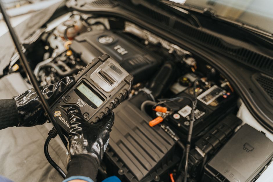
Mastering Automotive Electrical Diagnostics: A Step-by-Step Guide To Using Your Multimeter For Vehicle Troubleshooting. This Post Will Walk You Through The Essential Techniques, Tools, And Settings Required To Confidently Test Your Car&039;s Electrical System, From Basic Voltage Checks To More Intricate Circuit Analysis, Ensuring You Understand Not Just How But Also Why Each Step Is Performed For Accurate Diagnosis.
Oct
Automotive electrical systems can seem daunting, but with the right approach and a fundamental understanding of how electricity works, you can diagnose many common issues yourself. Your primary tool for this will be a digital multimeter, often referred to as a DMM or simply a multimeter. This versatile device allows you to measure voltage, resistance, and current, which are the three pillars of electrical diagnostics. Before you begin, always ensure your vehicle is in a safe, well-lit area and consider disconnecting the battery's negative terminal if you are working on a circuit where accidental shorts could occur, especially when measuring resistance or current.
A digital multimeter typically features a dial to select various functions and ranges, two test leads (one red and one black), and a display screen. For automotive work, the most frequently used settings are DC Volts (direct current voltage), Ohms (resistance), and sometimes Amps (current). When measuring DC Volts, you will usually find multiple ranges, such as 2V, 20V, 200V, and 1000V. Since most automotive systems operate at 12 volts, selecting the 20V DC range on a manual ranging multimeter is ideal, as it provides sufficient resolution without exceeding the meter's capacity. Auto-ranging multimeters will automatically select the appropriate range for you.
To measure DC Voltage, connect the red test lead to the VΩmA jack and the black lead to the COM (common) jack on your multimeter. Turn the dial to the DC Volts setting, selecting the 20V range if it's a manual meter. To test a battery, place the red probe on the positive terminal and the black probe on the negative terminal. A healthy battery should read around 12.6 volts when fully charged and the engine is off. When testing a circuit, such as checking for power at a light bulb socket, place the red probe on the power wire and the black probe on a known good ground point, like a metal part of the chassis. Always connect the multimeter in parallel with the circuit or component you are testing for voltage, meaning the circuit remains intact and powered.
Measuring Resistance, or Ohms, is performed to check for continuity in a wire or the internal resistance of a component like a sensor or a coil. Before measuring resistance, it is absolutely critical to ensure the circuit or component is completely de-energized; disconnect the battery or unplug the component from its power source. Connect the red test lead to the VΩmA jack and the black lead to the COM jack, then turn the dial to the Ohms (Ω) setting. You can place the probes on either end of a wire to check for continuity; a reading near 0 Ohms indicates a good connection, while an "OL" (open loop) or infinite resistance indicates a break in the wire. For components, consult a service manual for the expected resistance values. Resistance measurements are always taken with the component isolated from power.
Measuring Current, or Amps, is often considered more advanced because it requires the multimeter to be connected in series with the circuit you are testing, meaning you must break the circuit and insert the meter into the path of the current flow. This is crucial as connecting an ammeter in parallel will create a short circuit and likely damage your multimeter or blow a fuse within it. For most automotive multimeters, the built-in amp function is limited to 10 or 20 amps, which is suitable for smaller circuits or parasitic draw tests. For higher currents, such as starter motor draw, a specialized inductive amp clamp that measures current without breaking the circuit is necessary. When measuring current, ensure the red lead is moved to the 10A or mA jack on your multimeter, depending on the expected current.
Beyond these basic measurements, understanding voltage drop testing is vital. This involves measuring the voltage difference across a wire, connector, or component while the circuit is under load. A significant voltage drop indicates excessive resistance in that part of the circuit, which can hinder proper operation. For instance, measuring the voltage between the battery positive terminal and the starter motor's input terminal while cranking will reveal any resistance in the cable. Always refer to your vehicle's specific wiring diagrams to understand circuit paths and expected values, as these are invaluable tools for pinpointing issues quickly and accurately.
In summary, mastering automotive electrical tests with a multimeter involves a systematic approach: always prioritize safety by disconnecting power when necessary, select the correct function and range on your multimeter, and understand whether to connect your probes in parallel (for voltage) or series (for current and resistance). Practice these techniques on known good circuits to build confidence before tackling complex diagnostic challenges. With patience and consistent application, you will develop the skills to efficiently troubleshoot and repair your vehicle's electrical system, saving time and money in the long run.
