
Style
Ignite Your Automotive Electrical Intuition: Mastering Diagnostics With Precision Tools
Oct
The intricate web of wires and electronic components within modern vehicles can seem daunting, yet understanding its language is key to effective diagnosis and repair. Gone are the days when a simple test light sufficed for most electrical issues. Today, with complex sensor arrays, control modules, and communication networks, technicians and DIY enthusiasts alike need sophisticated tools to accurately pinpoint problems. Two indispensable instruments stand out in this electrical detective work: the multimeter and the oscilloscope, each offering a unique perspective into the vehicle's electrical pulse.
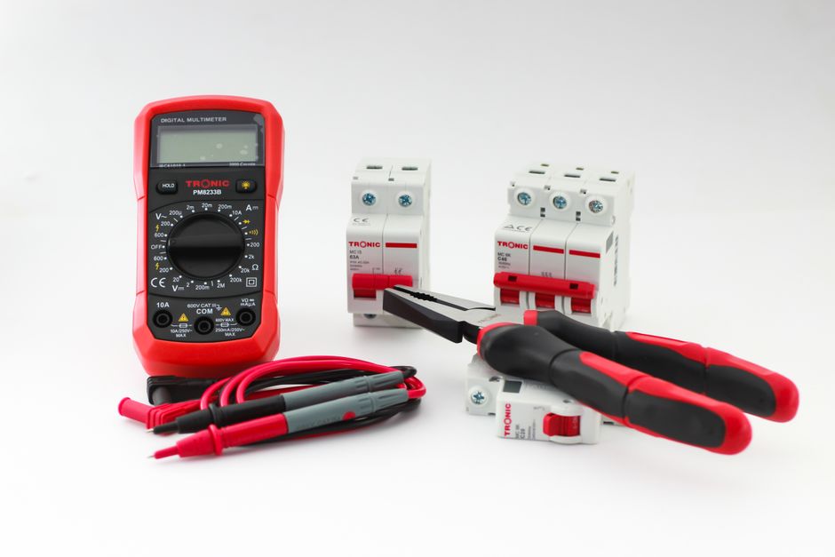
A multimeter, often the first tool acquired by anyone delving into automotive electrics, is a versatile device designed to measure fundamental electrical properties. It typically allows you to measure voltage (volts), resistance (ohms), and current (amperes). Think of it as a digital snapshot camera for electricity; it provides precise numerical readings of these values at a specific moment in time. For instance, you can use it to check a battery's voltage, test for continuity in a wire, or measure the resistance of a sensor or relay coil. Its strength lies in its accuracy for steady-state measurements and its straightforward digital display, making it excellent for verifying static conditions.
In contrast, an oscilloscope is a far more advanced diagnostic tool, best described as an electrical camcorder. Instead of a single numerical value, it displays an electrical signal as a waveform, plotting voltage against time on a graphical screen. This dynamic view allows you to see how a voltage changes over milliseconds or even microseconds, revealing crucial information about signal integrity, frequency, duty cycle, and transient events that a multimeter would completely miss. It excels at diagnosing intermittent faults, analyzing sensor outputs (like crankshaft position or oxygen sensors), checking injector pulse widths, and examining communication signals on networks such as CAN bus.
The fundamental difference, therefore, lies in their display and the type of information they convey. A multimeter gives you a single number, a static value, perfect for confirming if a component has the correct resistance or if a circuit has proper voltage. An oscilloscope, however, shows you the behavior of the signal over time, making it indispensable for understanding how components are actually functioning dynamically. You might use a multimeter to confirm a sensor has power and ground, but an oscilloscope would show if that sensor is producing a clean, accurate signal as the engine runs. They are not interchangeable but rather complementary tools, each filling critical gaps in diagnostic capability.
When approaching automotive electrical testing, safety is paramount. Always disconnect the battery if working on circuits that could short or cause damage, and wear appropriate personal protective equipment. The first step in any diagnosis should involve consulting the vehicle's service manual and, crucially, its wiring diagrams or schematics. These diagrams are your roadmap, illustrating the flow of electricity, component locations, and expected values. With a multimeter, basic tests include checking battery voltage (connect in parallel across the terminals), testing for voltage drop across a circuit (measuring voltage before and after a component or wire segment), and checking continuity (with the circuit de-energized, connect probes to either end of a wire or component to ensure a complete path). For current measurement, the multimeter must be connected in series, breaking the circuit to allow current to flow through the meter, which can be more complex and is often avoided unless necessary due to potential for meter damage.
Moving to the oscilloscope, its application often begins where the multimeter leaves off. To test a sensor, for example, you would connect the oscilloscope's probe in parallel with the sensor's signal wire and ground. As the component operates, the oscilloscope will draw a waveform. For a crankshaft position sensor, you might expect a square wave or sine wave that changes frequency with engine speed. An oxygen sensor might show a fluctuating voltage between 0.1V and 0.9V. Interpreting these waveforms involves understanding the expected pattern, amplitude (voltage height), frequency (how often it cycles), and duty cycle (percentage of time the signal is high versus low). The ability to see noise, glitches, or dropouts in a signal instantly reveals issues that a multimeter could never detect, such as intermittent shorts or open circuits. Proper setup of the oscilloscope's voltage scale (volts per division) and time base (seconds per division) is critical to capturing a clear and meaningful waveform.
Ultimately, mastering automotive electrical diagnostics requires a blend of knowledge, practice, and the right tools. Both the multimeter and the oscilloscope are invaluable, but they serve different purposes and provide distinct types of information. While the multimeter offers precision for static measurements, the oscilloscope provides dynamic insight into signal behavior, revealing the true operational health of complex electronic systems. Always start with a solid understanding of basic electrical principles, diligently consult wiring diagrams, and practice using both instruments on known good circuits. With patience and methodical troubleshooting, you will unlock the secrets of automotive electrics, transforming daunting problems into solvable puzzles.
